
Space enthusiasts fondly remember the Saturn V rocket which sent nine Apollo crews to the Moon including a dozen astronauts who actually landed on the lunar surface between July 1969 and December 1972. Retired after thirteen flights when it launched NASA’s Skylab space station into Earth orbit on May 14, 1973, it is frequently claimed that the Saturn V had a perfect flight record – an unequaled achievement for what was the largest launch vehicle of its day (see “The Largest Launch Vehicles Through History”). While it is certainly true that no Saturn V suffered a catastrophic failure which resulted in the total loss of a mission, NASA’s famous Moon rocket did experience its share of problems.

The final launch of the Saturn V on May 14, 1973 placed the Skylab space station into orbit. (NASA)
By far the most problem-filled flight of the Saturn V was that of Apollo 6 also known as “AS-502” in planning documents. This second unmanned launch of the Saturn V was meant to complete the flight testing of this new rocket needed to certify it for the upcoming crewed Apollo lunar missions. After the very successful initial test flight of Apollo 4 launched on November 9, 1967 (see “Apollo 4: The First Flight of the Saturn V”), it was expected that the second Saturn V, designated SA-502, would meet its goals allowing the first manned flights to start before the end of 1968. Unfortunately, the flight experienced a number of significant problems which almost resulted in an automated abort during ascent and later forced the Apollo 6 spacecraft to fly an alternate mission. While not an outright failure, this was the closest NASA’s Moon rocket would come to it during its otherwise successful 5½ year career.
The Apollo Mission Hardware
The most significant piece of hardware to be tested during the Apollo 6 mission was its launch vehicle. The three-stage Saturn V was the brainchild of the team of engineers led by famed German rocket pioneer, Wernher von Braun, at NASA’s Marshall Space Flight Center (MSFC) in Huntsville, Alabama which had previously developed the Saturn I and upgraded Saturn IB heavy-lift launch vehicles. Based on studies started in May 1961 after President Kennedy had committed the nation to a manned lunar landing by the end of the decade, work on the Saturn V began in earnest by the end of 1962 after months of studying the various options available.

Cutaway diagram showing the major components of the Saturn V. Click on image to enlarge. (NASA/MSFC)
The first stage of the Saturn V was designated the S-IC stage. While Boeing was selected as the prime contractor to construct a pair of non-flight stages and 13 flight models of the S-IC, the initial batch of non-flight and the first two flight models (including the stage used for the Apollo 4 and 6 missions) were assembled in house by MSFC, much as had been done in the early days with the Saturn I. The S-IC was a cylinder with a diameter of ten meters and a length of 42 meters carrying 1,196 metric tons of RP-1 and liquid oxygen (LOX). Its five F-1 engines built by Rocketdyne (which was then a division of North American Aviation and is today part of Aerojet Rocketdyne) generated 33,360 kilonewtons of thrust at lift off for this first test flight – almost five times the lift off thrust of the Saturn IB with its eight Rocketdyne H-1 engines. The purpose of the S-IC was to get the huge rocket off of the ground and start it on its way during a nominal 150-second burn that would get the ascending rocket to an altitude of about 62 kilometers and a speed of 2.7 kilometers per second.

Cutaway diagram showing the major components of the S-IC stage. Click on image to enlarge. (NASA/MSFC)
The second stage of the Saturn V was designated the S-II stage with North American Aviation as its prime contractor (which merged with Rockwell in March 1967 and subsequently with Boeing 29 years later). Unlike the S-IC and most earlier rockets, the S-II burned the high-energy combination of liquid hydrogen and LOX which yields about half again as much thrust as a like mass of more conventional propellants. With the same ten meter diameter as the S-IC stage, this stage was 24.8 meters long and carried 429 metric tons of cryogenic propellant. Its five Rocketdyne J-2 engines generated a total of about 4,450 kilonewtons of thrust in its initial versions. With a nominal burn time of 367 seconds, the S-II provided most of the energy to drive the rocket and its payload towards Earth orbit during an Apollo lunar mission with burnout occurring at a typical altitude of 185 kilometers and a speed of 6.8 kilometers per second.

Cutaway diagram showing the major components of the S-II stage. Click on image to enlarge. (NASA/MSFC)
The third stage of the Saturn V, with the Douglas Aircraft Company as the prime contractor (which, after decades of mergers, is now also part of Boeing), was designated the S-IVB stage. It had a diameter of 6.6 meters, a length of 17.8 meters and was connected to the S-II stage by a tapered interstage section. It carried 104 metric tons of cryogenic propellants for a single, restartable J-2 engine which would burn briefly during ascent with a thrust of 890 kilonewtons on its initial flights to place itself and its payload into a temporary Earth parking orbit and then later reignite to push on towards the Moon. The S-IVB stage also included a pair of auxiliary propulsion system (APS) modules each with a trio of hypergolic-fueled 670-newton engines which provided roll control during the burn of the J-2 as well as attitude control along all three axes while coasting in orbit. Each APS also included a 310-newton ullage engine to help settle the propellants in their tanks prior to reigniting the J-2 engine.

Cutaway diagram showing the major components of the S-IVB stage. Click on image to enlarge. (NASA/MSFC)
The Saturn V was topped off by the Instrument Unit (IU), with IBM as the prime contractor, which contained the guidance and command systems which controlled all three stages of the launch vehicle during all aspects of flight. Based on earlier work for the Saturn I and IB rockets, the IU incorporated the latest innovations in miniaturized electronics. The IU was designed to guide the Saturn V during its flight and would automatically adapt to problems encountered during ascent to ensure that its payload was placed into the proper orbit. The total height of the Saturn V with its Apollo payload attached was 111 meters and, for this second flights, it had a liftoff mass of 2,816 metric tons including its payload.

Cutaway diagram showing the major components of the Saturn V Instrument Unit (IU). Click on image to enlarge. (NASA/MSFC)
While testing the Saturn V dominated the objectives of the Apollo 6 mission, there were also important tests of the Apollo spacecraft itself. Originally, there were two versions of the Apollo spacecraft being built by its prime contractor, North American Aviation. The first variant, designated Block I, was essentially a prototype meant for test flights in low Earth orbit for the purpose of verifying the basic Apollo CSM (Command-Service Module) design. Lessons learned from constructing and flying these versions would be then incorporated into the improved Block II CSM which would include all of the equipment required to support a flight to the Moon.
The Apollo CM (Command Module), which carried the astronauts during their mission as well as the recovery systems needed to return them safely to Earth, was conical in shape with a diameter of 3.9 meters and a height of 3.2 meters. The SM (Service Module), which included all the systems and consumables needed to support the astronauts and their mission, was a cylinder with the same diameter. Its appearance was dominated by the 91-kilonewton Aerojet AJ10-137 engine of the Service Propulsion System (SPS) which would be used for all major propulsive maneuvers after the Saturn launch vehicle had finished its task. The total height of the CSM was 11 meters.

Cutaway diagram showing the major components of the Apollo spacecraft. Click on image to enlarge. (NASA/MSFC)
During the initial stages of the ascent, the Apollo spacecraft was topped off by the launch escape system (LES) built by the Lockheed Propulsion Company (whose corporate parent is now part of Lockheed Martin). It consisted of a solid rocket motor assembly attached to the top of the CM by means of a truss framework with a total height of 9.9 meters and a mass of 4,040 kilograms. It was designed to pull the CM and its crew to safety in case of an abort situation during the earliest phases of launch and would be jettisoned during the burn of the Saturn V second stage when it was no longer needed. The LES included a lightweight boost protective cover (BPC) made of fiberglass and cork which protected the outer hull and windows of the CM during the early phases of ascent and when the LES was jettisoned.
A tapered 8.5-meter tall Spacecraft Launch Adapter (SLA) consisting of four aluminum honeycomb panels 4.4 centimeters thick connected the S-IVB stage to the Apollo CSM during the launch phase of the mission. The LM (Lunar Module) would also be housed inside this adapter beneath the SM and its four panels would hing open to provide access after Apollo was on its way. Built by Grumman Aircraft, the LM was designed to land a pair of astronauts on the lunar surface and return them back to orbit and the awaiting CSM after a couple of days of exploration. It consisted of a descent stage with its own propulsion system and landing gear to get from lunar orbit to a soft landing and an ascent stage which housed and supported the astronauts along with its own propulsion system to lift off the lunar surface and return to orbit.

The first Apollo-Saturn IB at LC-34 ready for the launch of the AS-201 mission in February 1966. (NASA)
The Block I Apollo spacecraft had been flown successfully in space three times before the flight of Apollo 6. The unmanned Apollo AS-201 mission launched on February 26, 1966 was the first spaceflight of a production model CSM as well as the first flight of its Saturn IB launch vehicle to be used to carry Apollo hardware into low Earth orbit for initial flight testing (see “The First Flight of the Apollo-Saturn IB”). While all the primary mission objectives were met by CSM-009 (Command-Service Module number 009), problems encountered during this 37-minute suborbital test flight, especially during the pair of burns of the SM’s SPS, forced a postponement of the follow on AS-202 mission in order to resolve the issues. The next unmanned Apollo-Saturn IB test flight, AS-202, launched CSM-011 on a 93-minute suborbital mission on August 25 which ended with a splashdown in the Pacific Ocean. The spacecraft met its mission objectives and the CM successfully executed a double-skip reentry profile certifying the CSM for manned orbital flight (see “AS-202: The Last Test Flight Before Apollo 1”).

The launch of Apollo 4 on November 9, 1967 from LC-39A at Kennedy Space Center. (NASA/KSC)
While the first (and only planned) manned flight of the Block I using CSM-012 for the Apollo 1 mission was cancelled after its crew was killed in a cabin fire on January 27, 1967 during what was suppose to be a routine countdown rehearsal (see “The Future That Never Came: The Unflown Mission of Apollo 1”), CSM-017 successfully flew the unmanned Apollo 4 mission on November 9, 1967 which tested the Saturn V in fight for the first time (see “Apollo 4: The First Flight of the Saturn V”). The flight also provided an opportunity to test the CM heatshield under conditions close to what it would experience during a return from the Moon. With the Block II Apollo spacecraft expected to make its debut during the first manned Apollo mission in the fall of 1968, Apollo 6 would turn out be the last mission for this initial variant of the CSM.
The Mission Plan
As was the case during the Apollo 4 mission, the main objectives for the unmanned Apollo 6 test flight can be summarized as basically to test the Saturn V and evaluate the CSM for key aspects of an actual flight to the Moon. The SA-502 launch vehicle was fitted with sensors to return about 2,800 different measurements of launch vehicle performance via 23 telemetry systems so that all aspects of the flight could be monitored. Also carried by SA-502 were a pair of television cameras and a half dozen motion picture cameras in recoverable capsules which would be used to document crucial staging events, the performance of the propulsion systems and the behavior of the LOX in the S-IC’s tank. The recoverable camera pods would be ejected from the ascending Saturn V after they had completed their work and recovered a various points downrange by US Navy’s USS Austin – the lead ship of a then-new class of amphibious transport dock ships commissioned just three years earlier.

Diagram highlighting the key aspects of the Apollo 6 (AS-502) mission. Click on image to enlarge. (NASA)
Apollo 6 would start its mission with a launch from Pad A at Launch Complex 39 (LC-39A) at the Kennedy Space Center in Florida – the same pad used for the Apollo 4 mission. The first and second stages along with an initial burn of the S-IVB would place this upper stage and its payload into a temporary 185-kilometer parking orbit where it would remain for two revolutions as would happen during an actual flight to the Moon. The S-IVB would then reignite for translunar injection (TLI) and enter an extended geocentric orbit with an apogee of around 517,000 kilometers (with the exact figure depending on the launch date) to simulate a trajectory to the Moon. This was unlike the Apollo 4 mission with a simulated TLI burn that was 30 second shorter and placed its payload into an extended orbit with an apogee of just 17,200 kilometers. With the major mission objectives involving the Saturn V completed, attention would then turn to testing of the Apollo spacecraft itself.

CSM-020 shown being prepared for the Apollo 6 mission. (NASA)
The Apollo spacecraft for this mission was designated “CSM-020” and actually consisted of CM-020 and SM-014 whose original matching CM-014 had been disassembled in 1967 to support the Apollo 1 accident investigation. With a fully fueled launch mass of 25.1 metric tons, it was about five tons lighter than CSM-017 flown on the Apollo 4 mission owing largely to a lighter propellant load required for the new mission. Although it was a Block I type Apollo which would not be employed in subsequent manned flights (a decision which predated the Apollo 1 accident), CSM-020 carried a number of modifications to flight test upgrades for the Block II series spacecraft instituted in the wake of the Apollo 1 accident.

Diagram showing the Apollo CM unified crew hatch flown for the first time on the Apollo 6 mission. Click on image to enlarge. (NASA)
One of the more important of these upgrades was a new unified crew hatch which could be quickly opened in just five seconds to allow rapid egress in case of an emergency. Flight tests of a simulated outer hatch panel and samples of seal materials had already been successfully conducted during the Apollo 4 mission and this flight would certify the new design for manned flight. CM-020 also carried three ablator test panels – two 10 by 23 centimeter panels near the umbilical area and another 31 centimeter high panel replacing the meteoroid window cover of the left crew window. These panels would test various light-weight heat shield materials for possible use on future spacecraft.
Since there would be no crew, the interior of CM-020 did not carry astronaut couches as well as some flight controls and instrumentation displays just like the earlier unmanned Apollo test flights. Fitted inside of the cabin was a 163-kilogram electromechanical Mission Control Programmer (MCP) that would execute a preprogrammed sequence of commands or respond to ground commands to put the Apollo spacecraft through its paces during independent flight. This design had been successfully used in the earlier AS-202 and Apollo 4 unmanned test flights. When problems were found with the new MCP built for Apollo 6, the refurbished unit used during the Apollo 4 mission was substituted making this the first piece of Apollo hardware to be flown into space twice.

Diagram showing the interior of CM-020 for the Apollo 6 mission with the electromechanical Mission Control Programmer (MCP). Click on image to enlarge. (NASA)
Also included inside CM-020 were window-mounted cameras to provide a visual record of various phases of the mission. A Maurer Model 220-G 70 mm camera fitted with a 76 mm lens of the same type flown during the Apollo 4 mission was mounted to the crew hatch window. Starting about 1½ hours after launch as Apollo 6 would make its first pass over Baja California, this camera would take one frame every 8.6 seconds for two hours of the Earth passing below to assess the use of landmarks as a navigation aid while coasting in a parking orbit. The CM’s left rendezvous window was fitted with 16 mm Millikan motion picture camera operating at ten frames per second. This would be activated when needed to monitor key events during the mission such as the separation of the LES, orbital insertion as well as during reentry to gauge the brightness of the reentry plasma plume and assess use of the Earth’s horizon as a attitude reference.

Diagram showing the locations and fields of view of the cameras carried in CM-20 for the Apollo 6 mission. Click on image to enlarge. (NASA)
Since the objectives of the Apollo 6 mission did not include the LM which had been flight tested for the first time during the Apollo 5 mission (see “Apollo 5: The First Flight of the Lunar Module”), a boilerplate model designated LTA-2R (Lunar Test Article-2R) was carried by SA-502 to simulate the mass and dynamic properties of this part of the payload. With a mass of 11.8 metric tons, LTA-2R consisted of a flight-type LM descent stage without landing gear topped by a ballasted aluminum structure to simulate the ascent stage. Originally built as LTA-2 by Grumman for use in vibration testing at MSFC, it was refurbished to become LTA-2R for use as a flightworthy stand-in for the LM in the Apollo 6 mission. The propellant tanks of the descent stage were filled with a water-glycol mixture and Freon to simulate the characteristics of fuel and oxidizer for the LM propulsion system. Instrumentation mounted on 36 points on LTA-2R would return data on the dynamics of the structure during the first 12 minutes of flight. No flight instrumentation was included in the simulated ascent stage structure. LTA-2R would remain attached to the spent S-IVB stage after separation of the CSM three minutes following the shutdown of the S-IVB after its simulated TLI burn.
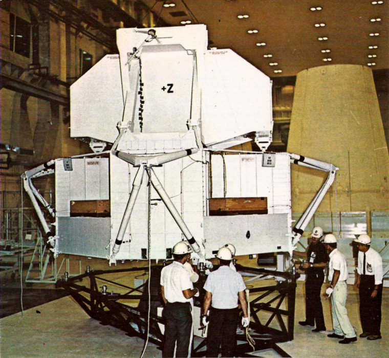
Engineers inspect the simulated LM payload for the Apollo 6 mission, LTA-2R, during launch preparations. (NASA)
After separating from its spent S-IVB stage, the Apollo 6 CSM would perform the first of two planned burns of the SPS. The first burn would slow the receding CSM from 10.67 to 8.59 kilometers per second. This would lower the apogee of Apollo 6 to 22,000 kilometers which would be reached six hours and 22 minutes after launch. During its coast in this new orbit, the CSM would turn its base towards the Sun to cold soak the CM as part of a test of the heat shield. Nine hours and 22 minutes into the fight, the CSM would reorient itself and fire the SPS for a second time. This three minute and 8 second burn would increase the velocity of Apollo 6 to 11.1 kilometers per second to simulate a return trajectory from the Moon for the upcoming CM heatshield test.
After the second burn of the SPS, Apollo 6 would be travelling at a less steep angle but about 52 meters per second faster than Apollo 4 during its reentry test. The chosen trajectory would result in a greater total heat load during reentry but a lower peak heating rate. After travelling about 4,600 kilometers downrange during reentry, the Apollo 6 CM would splashdown in the Pacific Ocean 630 kilometers north-northwest of Kuai, Hawaii about nine hours and 49 minutes after launch. The CM would then be recovered and eventually returned for post-flight assessment at North American’s facility in Downey, California where CM-020 was built. With its test objectives met, the flight of Apollo 6 would clear the way for the series of crewed test flights needed to land a astronauts on the lunar surface is less than two years.
Getting the Mission Off the Ground
The first piece of flight hardware for the Apollo 6 mission to arrive at Cape Kennedy (which reverted to its original name of Cape Canaveral in 1973) was the third stage of SA-502, designated S-IVB-502, on February 21, 1967. Next to arrive was the S-IC-2 first stage on March 13 which was erected on Mobile Launch Platform 2 (MLP-2) four days later. With SA-501 still being prepared on MLP-1 for the Apollo 4 mission later in the year, this would be he first time that there were more than one Saturn V inside the huge VAB (Vehicle Assembly Building) at LC-39. On March 20, IU-502 arrived at the Cape.

The S-IC-2 stage for the Apollo 6 mission shown after its delivery to the VAB. (NASA)
At this point, the delivery of the first two S-II stages from North American was running months behind schedule due to problems encountered during final assembly and testing. In order to keep the processing of the first pair of Saturn V rockets on track, it had been decided that the initial stacking of AS-501 would instead use a substitute – a S-II simulator designated H7-17 which had been originally constructed for handling training and test facility fit checks. The H7-17 test article basically consisted of a small diameter, load-bearing center column with S-II interfaces at either end giving the article a distinct spool-like shape. Modifications would make it suitable for use in the initial stacking and ground testing of the Saturn V.
A view of the S-II-spacer used as a temporary substitute in the initial stacking of SA-501 and SA-502 because of the late delivery of their respective S-II stages. (NASA)
After being removed from AS-501 on February 13, 1967, the S-II spacer was added atop of S-IC-2 on March 29 so that stacking of AS-502 could be completed and initial testing of the second Saturn V could proceed. The S-II-2 stage finally arrived at Cape Canaveral on May 24 and, after completing an inspection of its liquid hydrogen tank for cracks on July 6, it was added to the launch vehicle on July 13 to begin the next round of preflight testing during the next six weeks. CSM-020 attached to its SLA with LTA-2R tucked inside was finally added to the stack on December 10.

Apollo 6 shown during its roll out from the VAB on February 6, 1968. (NASA)
With its initial integrated tests completed, Apollo 6 was rolled out to LC-39B on the morning of February 6, 1968 and reached Pad A by about 6 PM EST. Building on the experience gained from preparing Apollo 4 for launch, prelaunch testing and checkout for Apollo 6 proceeded quickly. With the completion of the nine-day long countdown demonstration test on March 31, all was set for launch on April 4.

Apollo 6 shown at sunset at LC-39A. (NASA)
The 24-hour countdown for the launch of Apollo 6 formally began at 1:00 AM EST on April 3, 1968. The countdown proceeded through to a prescheduled six-hour hold at the T-8 hour mark with the problems encountered being quickly remedied without the need for additional holds. After resuming at 11:00 PM EST, the countdown continued without incident until liftoff at 7:00:01 AM EST (12:00:01 GMT) on the morning of April 4.

The launch of Apollo 6 on April 4, 1968 from LC-39A at Kennedy Space Center, Florida. (NASA)
Apollo 6 lifted off smoothly and cleared the tower after performing a yaw maneuver to provide a bit more clearance for the ascending Saturn V. Fortunately, the modifications made to the pad facilities resulted in much less damage on MLP-2 than MLP-1 had experienced during the Apollo 4 launch five months earlier. At 11.1 seconds after launch, SA-502 began a 20-second roll maneuver to align itself to the proper azimuth so that it could begin to slowly pitch over and start travelling downrange. While all seemed to be going well with the flight, at the 110-second mark the ascending rocket began to experience a longitudinal oscillation known as pogo. Superimposed on the steadily growing acceleration curve was an oscillation with a frequency in the 5.2 to 5.5 hertz range which reached a peak amplitude of ±0.6 g about 125 seconds into the flight – over six times larger than the same effect experienced by Apollo 4. This was much higher than the ±0.25 g upper limit permitted during earlier manned missions and would have been intolerable for any crew. If Apollo 6 had carried astronauts, it would have certainly been aborted at this point.

The Launch Control Center at LC-39 during the Apollo 6 launch. (NASA)
But as the longitudinal oscillations began to die out and finally reach acceptable levels 140 seconds after launch, ground-based and airborne cameras tracking the ascending Saturn V noted several pieces of debris coming off from the area of the SLA just after 133 seconds of flight. At about this time, the emergency detection system (which was flying in an automated closed-loop configuration for the first time) cast one vote for aborting the mission which would have been mandatory had a second vote been cast. Changes in the telemetry readings indicated that the outer skin of one of the SLA panels had debonded and separated from the rocket. Fortunately, the SLA maintained its overall structural integrity allowing the ascent to continue.

This still from footage from an airborne camera shows debris coming from the SLA during ascent. Click on image to enlarge. (NASA)
The center engine of the S-IC stage shutdown as expected 144.9 seconds after launch followed by the outer four F-1 engines at 148.4 seconds. After operating for just 1.1 seconds longer than planned and travelling just 7.3 meters per second faster than nominal, the S-IC stage was separated 149 seconds after launch at an altitude of 60.1 kilometers. The S-IC-2 had completed its task and fell to Earth breaking up about 397 seconds after launch at an altitude of 28.9 kilometers some 611 kilometers downrange. Aside from the 30 seconds of excessive vibration and the failure of three of its four camera pods to eject from the falling stage, S-IC-2 had met its objectives.

A still from footage documenting the separation and ignition of the S-II stage during the Apollo 6 mission. (NASA)
After casting off its spent first stage, the five J-2 engines of the S-II stage ignited 149.8 seconds after launch as Apollo 6 continued to accelerate towards orbit. At 184.8 seconds after launch, the LES separated since it was no longer needed to support abort options for the rest of the mission. All was going well until the 319-second mark when the fuel flow rate on engine J-2044 in the #2 position on the S-II stage suddenly increased at the same time its thrust decreased. Following a spike in the engine bay temperature, engine #2 shut down after running for 263.8 seconds out of a planned 368.8-second burn. Although it was showing no signs of trouble, engine J-2508 in the #3 position also shutdown 1.3 seconds later. After the loss of two J-2 engines, the Saturn V guidance system did its best to cope with the situation. While never configured to deal with the loss of two J-2 engines, Apollo 6 continued its ascent. Finally, the remaining three engines of S-II-2 shutdown nine minutes and 36.3 seconds after lift off. With the three remaining engines burning for 58.8 seconds longer than planned, Apollo 6 was travelling 102.3 meters per second slower than expected due to the lower acceleration while being 436.8 kilometer farther downrange and 6.4 kilometers higher because of how the guidance system tried to cope with the unexpected situation.
After separating from the now spent S-II stage, the single J-2 engine of S-IVB-502 ignited just a second after the S-II engines shutdown to continue the troubled ascent to orbit. The guidance system continued to attempt to get Apollo 6 back on course to reach a 185-kilometer parking orbit despite being too high and travelling too slow. Finally at 12 minutes and 27 seconds after launch, the S-IVB shutdown after burning almost 29 seconds longer than planned. Instead of being in a circular 185-kilometer circular orbit, Apollo 6 was in a more eccentric 173.0 by 356.8 kilometer orbit. Despite this off-nominal orbit and the longer than expected burn time, enough propellant remained in the S-IVB to proceed with the mission and perform the TLI burn near the end of the second revolution.

View of the area around Dallas-Fort Worth, Texas as photographed from Apollo 6 while travelling in its parking orbit. (NASA/JSC)
Once in orbit, the APS on the S-IVB stage was used to perform a series of attitude changes as part of the landmark navigation exercise. The 70 mm Maurer camera mounted in the CM crew hatch window was activated at key points to acquire swaths of images across the US, Atlantic Ocean and Africa. In addition to supporting the navigation exercise, the overlapping images allowed the creation of stereo views of clouds and the terrain below which were eventually used to support various scientific investigations. Once these tasks were completed, the S-IVB reoriented itself and its attached payload into a nose-forward attitude with its long axis aligned with the local horizontal.

This is an anaglyphic 3D image (left eye red, right eye blue) created with modern digital imaging techniques using a pair of images taken by Apollo 6 from its parking orbit. It shows afternoon thunderstorms forming over the Congo in Africa. Click on image to enlarge. (NASA/JSC/A.J. LePage)
After completing two revolutions, the plan was for the S-IVB stage to reignite for a 315-second burn which would send Apollo 6 into a simulated translunar trajectory with an apogee 528,000 kilometers which was intentionally directed away from the actual position of the Moon to simplify navigation. At a mission elapsed time of three hours, 13 minutes and 34.7 seconds, the command to reignite the J-2 engine was given but nothing happened. An apparent failure in the stage’s primary and auxiliary hydraulic systems had prevented the restart and the guidance system cancelled the ignition command 15.6 seconds later. There would be no TLI burn on this mission after all.
The Alternate Mission & Aftermath
With TLI not possible, ground controllers immediately moved to a preplanned alternative mission in order to meet as many objectives as possible. About 53 seconds after the failed reignition attempt, the CSM separated from the now useless S-IVB stage to continue the mission. The spent S-IVB-502 and its attached LTA-2R received the COSPAR designation of 1968-025B and continued in its decaying orbit until April 26 when it came down over the Indian Ocean. The now freed CSM ignited its SPS at a mission elapsed time of three hours, 16 minutes and 6.2 seconds for a 441.7-second burn to increase the velocity of Apollo 6 by 1,785 meters per second. This placed Apollo 6 into a new orbit with an apogee of 22,260 kilometers – similar to what was originally planned with the combination of the TLI and subsequent retrograde maneuver by the SPS. With a perigee of just 33 kilometers, the new orbit would ensure that the CM would reenter Earth’s atmosphere over the Pacific Ocean. Unfortunately, there was insufficient propellant remaining for the SPS to fire a second time in this alternate mission to accelerate the CM for a more punishing reentry test.

Scene at the flight operations director’s console in the Mission Control Center at the Manned Space Center (MSC – today known as the Johnson Space Center) during the Apollo 6 mission. Left to right, are USAF Maj. Gen. Vincent G. Huston, Dr. Christopher C. Kraft, Jr., George M. Low and Dr. Robert R. Gilruth.(NASA/JSC)
Following the SPS burn, Apollo 6 aligned its base towards the Sun to begin a six-hour cold soak of the CM heat shield. As Apollo 6 climbed towards apogee which was reached 6½ hours after launch, instruments monitored how effectively the CM hull shielded the interior cabin from radiation in the Van Allen belts. During the daylight pass, the 70 mm Maurer camera secured an additional 370 photographs of the Earth below. As Apollo 6 neared the atmosphere, the CM and SM separated 9 hours, 36 minutes and 56.6 seconds after launch. After aligning itself with its blunt heat shield forward, the Apollo 6 CM began reentry 92.4 seconds later at an inertial velocity of 10.0 kilometers per second.

A still from footage showing the view out of the left rendezvous window during the reentry of Apollo 6 with the limb of the Earth visible to the left. (NASA/JSC)
The CM’s guidance system steered the descending spacecraft through reentry and towards its landing zone. The parachutes were deployed and Apollo 6 splashed down at 21:57:21 GMT in the Pacific at 158.0° W, 27.7° N about 91 kilometers uprange from its recovery ship, the Iwo Jima-class amphibious assault ship, USS Okinawa. The total length of the mission was nine hours, 57 minutes and 19.9 seconds – about eight minutes longer than originally planned. Apollo 6 was spotted by fixed-wing search aircraft 26 minutes after splashdown with rescue swimmers arriving by helicopter at about 23:43 GMT to secure the CM as it bobbed in 1.2 meter swells. Apollo 6 was finally hoisted onboard the USS Okinawa about six hours after the end of its mission.

The Apollo 6 CM shown as it is about to be hoisted on board the USS Okinawa following its successful splashdown. (NASA)
Although Apollo 6 mission had ended with a successful recovery (and had a crew been carried, they would have survived as well), the flight had revealed a number of potentially serious problems with the Saturn V which had to be addressed. Such a resolution was urgently needed to maintain NASA’s increasingly aggressive schedule to reach the Moon before the end of the decade. Even as Apollo 6 completed its troubled flight, ground crews at LC-34 were already preparing to stack the SA-205 Saturn IB launch vehicle for the first manned flight in Earth orbit (see “Apollo 7: Rise of the Phoenix“) and the next Saturn V, SA-503, had already been stacked in the VAB and was three months into its initial check out for its first manned Saturn V mission (see “Apollo 8: Where No One Has Gone Before“).
Investigation of the strong pogo effect noted during the burn of the S-IC was eventually found to be the result of the F-1 engines. The five engines of the S-IC were purposely tuned to slightly different frequencies near 5½ hertz to avoid strong resonant vibrations as the stage’s propellant tanks emptied during ascent. It turned out that two of the F-1 engines had been inadvertently tuned to the same frequency which enhanced the pogo effect. In addition to modifying procedures to ensure that the F-1 engines were properly “detuned”, extra helium was added to the cavities in the LOX prevalve assemblies to act as pneumatic shock absorbers to suppress strong variations in LOX flow which was a significant cause of pogo in the Saturn V. These pogo-suppressing modifications were evaluated using S-IC-4 (which would serve as the first stage of the launch vehicle for the Apollo 9 mission) during test firings at the Michoud Assembly Facility in Louisiana in August 1968 and subsequently made to S-IC-3 at the VAB for the Apollo 8 mission.

This diagram indicates the areas of the Apollo 6 SLA which showed darkening in launch photograph as a result of a band failure during ascent. Click on image to enlarge. (NASA)
The problem with the SLA shedding parts of its outer skin during ascent was found to be due to a splice plate bond void in its honeycomb aluminum panels. Moisture had built up inside of the honeycombed structure resulting in an increase in pressure as the panel experienced aerodynamic heating during ascent. With no way to relieve the pressure, the panel’s skin failed at a splice and blew off. This problem was solved in the SLA to be used on the Apollo 7 mission (which would experience a less stressful environment during ascent on the Saturn IB) by drilling a series of holes in the panels to help equalize the pressure. On the SLAs to be used on Apollo 8 and subsequent Saturn V flights, a layer of cork was also added to the panels to help keep them cooler and absorb moisture.
After much detective work reviewing the telemetry returned during the ascent on the S-II stage, the problem with the J-2 engine #2 shutdown was found to be due to a failure in the flexible bellows in the fuel line which fed liquid hydrogen to the engine’s augmented spark igniter (ASI). The ASI was mounted in the engine’s injector assembly to ignite the propellants inside of the J-2 thrust chamber. The fuel line was strengthened and redesigned to eliminate the bellows which were found to be prone to cracking when vibrating in the near-vacuum conditions during the S-II burn (a failure mode that was missed during ground testing of the J-2 engines).

This drawing compares the old J-2 augmented spark igniter fuel line (with the bellows which failed during the flight of Apollo 6) and the new design which was strengthened and omitted the bellows. Click on image to enlarge. (NASA)
The unexpected shutdown of the J-2 #3 on S-II-2 just a second after #2 was found to be due to a wiring error. When the problem with engine #2 was detected, the IU sent commands to shutdown the J-2 by stopping its flow of propellants. While the flow of liquid hydrogen to engine #2 was stopped, the LOX prevalves of engines #2 and #3 had been accidentally crosswired so that the flow of LOX to engine #3 had been shut off instead resulting in an unintended shutdown. On April 29, 1968, the S-II-3 stage for the upcoming Apollo 8 mission was destacked and shipped back to the Mississippi Test Facility for detailed inspection, modifications and additional testing to “man rate” the stage. S-II-3 was returned to the Cape on June 27 ready for flight.

The S-II-3 stage shown being restacked on July 24, 1968 after it was returned to the VAB following modifications and inspections to “man rate” the stage for the Apollo 8 mission after problems were uncovered during the Apollo 6 mission. (NASA)
The failure of the J-2 engine on the S-IVB-502 stage to reignite was also traced to a failure in the ASI fuel line. A crack in the bellows had allowed cryogenic liquid hydrogen to leak out after its initial firing and freeze the fluid in nearby hydraulic lines. The resulting blockage prevented the hydraulic system from functioning to allow reignition of the J-2 engine. The changes made to the ASI fuel line design in response to the problems with the S-II would also fix the problem with the S-IVB. With the successful ground testing of the various changes made in the wake of the Apollo 6 mission, the Saturn V was deemed ready for its first flights with a crew bringing NASA one step closer to its goal of landing astronauts on the Moon before the end of the decade.
Follow Drew Ex Machina on Facebook.
Related Video
This video is the Saturn Quarterly Film Report Number 36 from June 1968 produced by NASA/MSFC. It includes information about the Saturn V performance during the Apollo 6 mission and the subsequent investigation and fixes for the problems encountered.
Here is the J-2 Engine Semi-Annual Film Report from August 1968 produced by NASA and Rocketdyne which provides details into the investigation of the cause of the J-2 engine failures during the Apollo 6 mission.
Related Reading
“Apollo 4: The First Flight of the Saturn V”, Drew Ex Machina, November 11, 2017 [Post]
“Apollo 5: The First Flight of the Lunar Module”, Drew Ex Machina, January 22, 2018 [Post]
“The Saturn 500F: The Moon Rocket That Couldn’t Fly”, Drew Ex Machina, September 23, 2016 [Post]
General References
Roger E. Bilstein, Stages to Saturn: A Technological History of the Apollo/Saturn Launch Vehicles, University Press of Florida, 2003
Courtney Brooks, James M. Grimwood and Loyd S. Swenson, Jr., Chariots for Apollo: The NASA History of the Manned Lunar Spacecraft to 1969, Dover Publications, 2009
Gene F. Holloway, Apollo Experience Report – Guidance and Control Systems: Mission Control Programmer for Unmanned Missions AS-202, Apollo 4, and Apollo 6, NASA TN D-7992, JSC-NASA, July 1975
Alan Lawrie with Robert Goodwin, Saturn V – The Complete Manufacturing and Test Records, Apogee Books, 2005
Richard D. Orloff and David M. Harland, Apollo: The Definitive Sourcebook, Springer-Praxis, 2006
Apollo 6 Scheduled, NASA Press Release 68-54, March 28, 1968
Final Flight Evaluation Report: Apollo 6 Mission, 02-117017-3 Rev. C, Office of Manned Space Flight, February 1969
S-II Engines 2 and 3 are adjacent; see Saturn V Launch Vehicle Flight Evaluation Report-AS-502 Apollo 6 Mission, Fig. 11-1 p. 11-4. Also, the photo labelled, “A still from footage showing the separation and ignition of the S-IVB stage during the ascent of Apollo 6 towards orbit.” is actually from a Saturn IB launch.
One of my later-date and usually reliable references stated the pair of J-2 engines were on opposite sides but you are indeed correct: I checked Rocketdyne’s report S-II Stage Failure Analysis (R-7450-2) dated June 17, 1968 and it clearly shows both engines were on the same side. I have corrected the text accordingly. I also checked into the image in question which I took from a video titled “Apollo 6 16mm Onboard Film”. I double checked a couple of references dealing with the placement of cameras on SA-502 and there does not seem to be a camera in the S-II/S-IVB interstage. Obviously the film was mislabeled and I have removed the image. Thanks for the corrections 🙂
SA-502 did not “almost fail”. It *did* fail. It failed to put its payload into its intended orbit, thanks to that failed S-IVB restart.
Yes, the S-IVB failed to restart but that did not result in the Apollo 6 mission being declared a failure. Had this been a lunar mission, the primary lunar objectives would certainly have failed to be achieved. But this was not one of the success criteria for the Apollo 6 mission. The SPS was able to be used to place the CSM into a high apogee orbit as part of an alternate mission plan so that CSM-020 was able to achieve or partially achieve all 33 of its primary and secondary mission objectives. Likewise, even with the numerous problems experienced by the S-II and S-IVB stages, SA-502 managed to achieve or partially achieve 16 out of its 18 primary and secondary objectives. By this measure, SA-502 did not fail and the Apollo 6 mission as a whole was not a failure.
Overshadowed by the assassination of Martin Luther King later in the day.
There’s another factor more important than leaking LH2 causing hydraulic fluid to freeze. The broken ASI fuel line made the igniter run LOX-rich, and thus far hotter than normal. This eroded the injector on S-II engine 2 until it failed. The engine on the S-IVB suffered from the same problem, but the initial burn wasn’t long enough for the excessive heat to cause the injector to fail. There was enough damage to the engine to prevent it from starting back up.
Wow! Amazing!
They had they spaceship??
I have an unrelated question about the photo showing the SLA debris. What looks like an apron of flames seems to engulf at least 3/4 of the first stage. I don’t recall seeing this on other Saturn V launch photos. Was this normal? Why would exhaust flames migrate so far “upstream” from the engines?
https://i0.wp.com/www.drewexmachina.com/wp-content/uploads/2018/04/S68-3817.jpg?ssl=1
“As the rocket gains altitude, the surrounding air pressure decreases. As the surrounding air pressure reduces, the pressure behind the rocket (from the exhaust plume) is great enough to force the rocket’s slip-stream to separate from the rocket’s body (called boundary layer separation). When the slip-stream is forced away from the rocket, the exhaust gases push up into the void.” – Reddit user Minotaurs
https://www.reddit.com/r/space/comments/5dygbh/the_underexpaned_exhaust_of_the_saturn_v_as_it/